Iranian Classification Society Rules

< Previous | Contents | Next >
Section 4 Hull Structural Design
401. Design ice pressures
1. Design ice pressure is not to be less than that obtained from the following formula: (MPa)
= a factor which takes account of the influence of the size and engine output of the ship.
(
![]()
= the displacement (ton) of ship on the maximum ice-class draught according to 202. 3
= engine output (kW).
and = as given in
Table 3.20.6 according to the region under consideration and
Table 1.6 Value of and
Bow | Midbody and Stern region | |||
≤ | ≤ | |||
30 | 6 | 8 | 12 | |
230 | 518 | 214 | 286 | |
= a factor which takes account of the probability that the design ice pressure occurs in a certain region of the hull for the Ice class in question, as given in Table 1.7 according to the Ice class and the region.
= the nominal ice pressure; the value 5.6 MPa is to be used.
= a factor which takes account of the probability that the full length of the area under con- sideration will be under pressure at the same time, as given by the following formula.
(0.35 1.0)
= to be taken as specified in
Table 1.7 Coefficient
Table 1.8 according to the structural member under
Structure | Type of framing | (m) |
Shell | Transverse | Frame Spacing |
Longitudinal | 1.7 frame Spacing | |
Frames | Transverse | Frame Spacing |
Longitudinal | span of frame | |
ice stringer | - | span of stringer |
web frame | - | 2-spacing of web frames |
Table 1.8 Value of
Ice class | Bow | Midbody | Stern |
IA Super | 1.00 | 1.00 | 0.75 |
IA | 1.00 | 0.85 | 0.65 |
IB | 1.00 | 0.70 | 0.45 |
IC | 1.00 | 0.50 | 0.25 |
ID | 1.00 | - | - |
![]()
Note : The frame spacings and spans are normally assumed to be measured along the plate and perpendicular to the axis of the stiffener for plates, along the flange for members with a flange, and along the free edge for flat bar stiffeners. For curved members the span (or spacing) is defined as the chord length between span (or spacing) points. The span points are defined by the intersection between the flange or upper edge of the member and the supporting structural element (stringer, web frame, deck or bulkhead). (see Fig. 1.3)
![]()
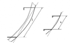
Fig 1.3 Definition of the frame span(left) and frame spacing (right) for curved members.
2. The is the height of the area under the ice pressure specified in Par 1 and is to be as given in Table 1.9 according to the Ice class.
Table 1.9 Value of
Ice class | (m) |
IA Super | 0.35 |
IA | 0.30 |
IB | 0.25 |
IC | 0.22 |
ID | 0.22 |
402. Shell plating
1. The vertical extension of ice belt is to be as given in is to comply with the following requirements.
Table
1.10 according to the Ice class and
Table 1.10 Vertical extension of the Ice belt
Ice class | Hull Region | Above UIWL | Below LIWL |
IA Super | Bow | 0.6 m | 1.2 m |
Midbody | |||
Stern | 1.0 m | ||
IA | Bow | 0.5 m | 0.9 m |
Midbody | |||
Stern | 0.75 m | ||
IB and IC | Bow | 0.4 m | 0.7 m |
Midbody | |||
Stern | 0.6 m | ||
ID | Bow | 0.4 m | 0.7 m |
(1) Fore foot
For Ice class IA Super the shell plating below the ice belt from the stem to a position five main frame spaces abaft the point where the bow profile departs from the keel line is to have at least the thickness required in the ice belt in the midbody region.
(2) Upper bow ice belt
For Ice classes IA Super and IA on ships with an open water service speed equal to or ex- ceeding 18 kt, the shell plate from the upper limit of the ice belt to 2 m above it and from the
![]()
stem to a position at least 0.2 abaft the bow perpendicular, is to have at least the thickness required in the ice belt in the midbody region. A similar strengthening of the bow region is to apply to a ship with lower service speed, when it is, e.g. on the basis of the model tests, evi- dent that the ship will have a high bow wave.
(3) Side scuttles are not to be situated in the ice belt.
(4) If the weather deck in any part of the ship is situated below the upper limit of the ice belt, the bulwark and the construction of the freeing ports are to be given at least the same strength as is required for the shell in the ice belt.
2. The thickness of shell plating in the ice belt is not to be less than that obtained from the follow- ing formula:
For the transverse framing : For the longitudinal framing :
: 2 mm, if special surface coating, by experience shown capable to withstand the abrasion of
ice, is applied and maintained, lower values may be approved.
: 0.75 (MPa)
as specified in 401. 1
: as given in the following formula. Where, however, is greater than 1.0, is to be tak- en as 1.0
: as given by the following formula depending on the value of
Where :
Where ≤ :
: as specified in Table 1.9.
: yield stress of the material of the member considered, which are given as follows
(N/mm2)
235 : for mild steels as specified in Pt 2, Ch 1 of the Rules for the Classification of
315 : for high tensile steels A H 32, D H 32, E H 32 or F H 32 as specified in Pt 2, Ch the Rules for the Classification of Steel Ships
355 : for high tensile steels A H 36, D H 36, E H 36 or F H 36 as specified in Pt 2, Ch the Rules for the Classification of Steel Ships
390 : for high tensile steels A H 40, D H 40, E H 40 or F H 40 as specified in Pt 2, Ch the Rules for the Classification of Steel Ships
1 of 1 of 1 of
403. Frames
1. Vertical extension of ice strengthening
![]()
(1) The vertical extension of ice strengthening of the framing is to be at least as given in Table
![]()
1.11 according to the respective Ice classes and regions. Where an upper bow ice belt is re- quired in 402. 1 (2) the ice strengthening part of the framing is to be extended at least to the top of this ice belt. Where the ice strengthening would go beyond a deck or a tanktop (or tank bottom) by no more than 250 mm, it can be terminated at that deck or tanktop (or tank bot- tom).
(2) Within the ice strengthening area all frames are to be effectively attached to all the supporting structures. A longitudinal frame is to be attached all the supporting web frames and bulkheads by brackets. When a transverse frame terminates at a stringer or deck, a bracket or similar con- struction is to be fitted. When a frame is running through the supporting structure, both sides of the web plate of the frame are to be connected to the structure by direct welding, collar
plate or lug. When a bracket is installed, it is to have at least the same thickness as the web plate of the frame and the edge is to be appropriately stiffened against buckling.
(3) For Ice class IA Super in all region, for Ice class IA in the bow and midbody regions and for
Ice classes IB, IC and ID in the forward regions, followings are to apply in the ice strengthen- ing area.
(A) The frames are to be attached to the shell by double continuous welds. No scalloping is al- lowed except when crossing shell plate butts.
(B) The web thickness of the frames is not to be less than the greatest of the following (a) to (d).
(a) , is the web
= 805 for profiles and
= 282 for flat bars
(b) 2.5 % of the frame spacing for transverse frames
(c)
half of the net thickness of the shell plating, . For the purpose of calculating the web thickness of frames, the required thickness of the shell plating is to be calculated according to 402.2 using the yield strength of the frames;
(d) 9 mm
(C) Where there is a deck, tanktop (or tank bottom) or bulkhead in lieu of a frame, the plate thickness of this is to be as per the preceding in (B), to a depth corresponding to the height of adjacent frames.
(D) Frames that are not normal to the plating or the profile is unsymmetrical, and the span ex- ceeds 4.0 m, shall be supported against tripping by brackets, intercostals, stringers or similar at a distance not exceeding 1.3 m. If the span is less than 4.0 m, the supports against trip-
ping are required for unsymmetrical profiles and stiffeners to plating in the following regions:
for web of which is not normal
IA Super IA
IB, IC and ID
All hull regions
Bow and midbody regions Bow region.
![]()
Table 1.11 Vertical extension of the ice strengthening of framing
Ice class | Region | Above UIWL(m) | Below LIWL (m) |
IA Super | Bow | 1.2 | to double bottom or below top of floors |
Midbody | 2.0 | ||
Stern | 1.6 | ||
IA IB IC | Bow | 1.0 | 1.6 |
Midbody | 1.0 | 1.3 | |
Stern | 1.0 | 1.0 | |
ID | Bow | 1.0 | 1.6 |
2. Transverse frames
(1) The section modulus and the effective shear area A of a main or intermediate transverse frame specified in 403. 1 is to be not less than that obtained from the following formula. Where less than 15 % of the span of the frame is situated within the ice strengthening zone for frames, ordinary frame scantlings may be used.
Section modulus: × (cm3)
Effective shear area: × (cm2)
= factor which takes into account the maximum shear force versus the load location and the shear stress distribution, taken as 1.2
= as specified in 401. 1.
= frame spacing (m).
= as specified in Table 1.9.
= span of the frame (m).
= as given by the following formula :
and
= as specified in Table 1.12. The boundary conditions are those for the main
intermediate frames. Load is applied at mid span.
= as specified in 402. 2.
(2) The upper end of the strengthening part of a main frame and of an intermediate frame are to be attached to a deck, tanktop (or tank bottom) or an ice stringer as specified in 404. Where a frame terminates above a deck or a stringer (hereinafter, referred to as the lower deck in this section) which is situated at or above the upper limit of the ice belt, the part of the frame above the lower deck is to be in accordance with the followings:
(A) the part of the main frame and the intermediate frame may have the scantlings required by the ordinary frame
(B) the upper end of the main frame and the intermediate frame is to be connected to a deck
which situated above the lower deck (hereinafter, referred to as the higher deck in this sec- tion). However, the upper end of the intermediate frame may be connected to the adjacent
![]()
(3) The lower end of the strengthened part of a main frame and of an intermediate ice frame is to be attached to a deck, tank top (or tank bottom) or ice stringer specified in 404. Where an in- termediate frame terminates below a deck, tank top (or tank bottom) or ice stringer which is situated at or below the lower limit of the ice belt, the lower end may be connected to the ad- jacent main frames by a horizontal member of the same scantlings as the frames. Note that the main frames below the lower edge of ice belt must be ice strengthened, see Par 1.
Table 1.12 Value of
Boundary condition | Example | |
Both ends fixed | 7.0 | Frames in a bulk carrier with top side tanks |
| ||
One side fixed and one side simple support | 6.0 | Frames extending from the tank top to a single deck |
| ||
Multi point simple support | 5.7 | Continuous frames between several decks or stringers |
| ||
Both ends simple support | 5.0 | Frames extending between two decks only |
|
3. Longitudinal frames
The section modulus and effective shear area of a longitudinal frame in the extension speci- fied in 403. 1 are not to be less than that obtained from the following formula. However in calcu- lating the actual shear area of the frames, the shear area of the brackets is not to be taken into account. When the effective flange used in calculating the section modulus of the longitudinal
frame in larger frame spacing is to be taken at most visions of 402.
. An attention is to be paid to the
× (cm3), × (cm2)
= factor which takes account of the load distribution to adjacent frames given by follow-
![]()
= as specified in Table 1.9.
= frame spacing (m). as specified in 401. 1.
= span of the longitudinal frame (m).
= as specified in 402. 2.
factor which takes account the maximum shear force versus load location and the shear stress distribution ( = 2.16)
= boundary condition factor is to be taken as 13.3. Where the boundary conditions de-
viate significantly from those of a continuous beam, a smaller boundary factor is to be adapted. For frames without brackets a value 11.0 is to be used. For frames in conditions deviating from those of continuous beam is to be determined in accordance with the followings:
(A)For conditions deemed as those fixed at both ends : =12
(B)For conditions deemed as those simple supported at both ends : =8
(C)For conditions other than (A) or (B), boundary condition factor is to be de- termined by calculation using simple beam theory, but in no case that is not to be greater than 13.3.
404. Ice stringers
1. The section modulus and the effective shear area of a stringer situated within the ice belt are to be not less than that obtained from the following formula:
× (cm3),
× (cm2)
= as specified in 401. 1.
= as specified in Table 1.9. However, the product is not to be taken as less than 0.15.
= span of the stringer (m).
= boundary condition factor; as given in 403. 3, for ice stringers in conditions deviating from those of continuous beam is to be determined in accordance with 403. 3 (2).
= factor which takes account of the distribution of load to the transverse frames is to be taken as 0.9.
= safety factor of stringer: to be taken as 1.8
= factor that takes into account the maximum shear force versus load location and the shear stress distribution: to be taken as 1.2
= as specified in 402. 2.
2. The section modulus and the effective shear area of a stringer situated outside the ice belt
but supporting ice strengthened mula:
frames are not to be less than that obtained from the following for-
(cm3), × 2
= as specified in 401. 1.
= as specified in Table 1.9.
0.15.
= span of the stringer (m).
However, the product is not to be taken as less than
![]()
= boundary condition factor; = as given in 403. 3.
= the distance to the adjacent ice stringer (m).
= the shortest distance from the considering stringer to the ice belt (m).
= factor which takes account of load to the transverse frames is to be taken as
= safety factor of stringer ; to be taken as 1.8
= factor which takes account the maximum shear force versus load location and the shear stress dis- tribution; = 1.2
= as specified in 402. 2.
3. Narrow deck strips abreast of hatches and serving modulus and shear area requirements in Par 1 and
as ice stringers are to comply with the section
2 respectively. In the case of very long hatch-
es, the product may be taken as less than 0.15 but in no case less than 0.1. Regard is to be paid to the deflection of the ship's sides due to ice pressure in way of very long(more than B/2) hatch openings, when designing weather deck hatch covers and their fittings.
405. Web frames
1. The ice load transferred to a web frame from an ice stringer or from longitudinal framing is not to be less than that obtained by the following formula. However, In case the supported stringer is outside the ice belt, the load may be reduced by multiplying .
= ice pressure (MPa) as specified in 401. 1 in calculating however, is to be taken as 2 .
= safety factor of web frames; to be taken as 1.8.
= as specified in Table 1.9. However, the product is to be more than 0.15.
= web frame spacing (m).
: As specified in 404. 2.
2. The section modulus and effective shear area of ing formula:
web frame may be obtained from the follow-
×
3 2
× (cm ),
= span of web frame (m).
= maximum calculated shear force under the ice load , as given in Par 1
= factor that takes into account the shear force distribution, = 1.1
= maximum calculated bending moment under the ice load ; to be taken as .
and = as given in Table 1.13. For intermediate values of linear interpolation.
= as specified in 402. 2.
= required shear area (cm2)
= actual cross sectional area of the web frame (cm )2
is to be obtained by
![]()
Table 1.13 Value of and
0.00 | 0.20 | 0.40 | 0.60 | 0.80 | 1.00 | 1.20 | 1.40 | 1.60 | 1.80 | 2.00 | |
1.50 | 1.50 | 1.23 | 1.16 | 1.11 | 1.09 | 1.07 | 1.06 | 1.05 | 1.05 | 1.04 | |
0.00 | 0.44 | 0.62 | 0.71 | 0.76 | 0.80 | 0.83 | 0.85 | 0.87 | 0.88 | 0.89 | |
Note: 2 = actual cross section area of free flange (cm ) 2 = actual effective cross section area of web plate (cm ) | |||||||||||
3. The scantlings of web frames may be calculated by direct analyses where deemed appropriate by the Society. In this case, the following are to be complied with;
(1)
The pressure to be used is 1.8 (MPa) where is determined according to 401. 1. The load patch is to be applied at locations where the capacity of the structure under the combined ef- fects of bending and shear are minimized.
(2) The structure is to be checked with load centered at the UIWL, 0.5 (m) below the LIWL,
positioned several vertical locations in between. Several horizontal locations which
tions centered at the mid-span or spacing are to be checked. If the load length
are the loca-
cannot
(3)
determined directly from the arrangement of the structure, several values of may be using corresponding values for .
The acceptance criterion for designs is that the combined stresses from bending and shear, us-
ing the von Mises yield criterion, are lower than . When the direct analysis is using beam theory, the allowable shear stress is not to be larger than 0.9· , where
406.
Bow
1. Stem
(1) The stem shall be made of rolled, cast or forged steel or of shaped steel plates as shown in
Fig. 1.4.
(2) The plate thickness of a shaped plate stem and in the case of a blunt bow, any part of the shell where angle and as specified in 302. 1 are respectively not less than 30 degrees and 75 degrees, is to be obtained from the formula in 402. 2 using the following values ;
= spacing of elements supporting the plate (m).
= ice pressure ( ) as specified in 401. (MPa).
= spacing of vertical supporting elements (m).
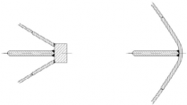
Fig 1.4 Examples of suitable stems
(3) The stem and the part of a blunt bow specified in Par 2 is to be supported by floors or brackets spaced not more than 0.6 m apart and having a thickness of at least half the plate thickness.
(4) The reinforcement of the stem is to be extended from the keel to a point 0.75 m above UIWL or, in case an upper forward ice belt is required in 402. 1 to the upper limit of this.
2. Arrangements for towing
![]()
Special consideration is to be given to the strength and installation of towing arrangements.
![]()
407. Stern
1. The clearance between the propeller blade tip and hull, including the stern frame is not to be less than as specified 203. to prevent from occurring high loads on the blade tip.
2. On twin and triple screw ships, the ice strengthening of the shell and framing are to the double bottom for 1.5 m forward and aft of the side propellers.
to be extended
3. On twin and triple screw ships, the shafting and stern tubes of side propellers are to be normally enclosed within plated bossings. If detached struts are used, their design, strength and attachment to the hull are to be duly considered.
4. The introduction of new propulsion arrangements with azimuth thrusters or podded propellers, which provide an improved maneuverability, will result in increased ice loading of the stern region and the stern area. This fact is to be considered in the design of the aft/stern structure.
408. Bilge keel
Special consideration is to be given to the design of bilge keels.


